Waters

How to disassemble an ACQUITY QDa - WKB244388

Article number: 244388

OBJECTIVE or GOAL

Shut down and disassemble a QDa detector for shipment to the repair center.

ENVIRONMENT

  • QDa 

PROCEDURE

  1. Close the control software and power-off the QDa. Wait a few minutes until the turbo molecular pump stops completely.
  2. Close the Nitrogen supply.
  3. Disconnect the QDa from the fluidics path and uninstall the probe.
  4. Remove the drain valve connection.
    • If you have a QDa with an external drain valve (serial number starts with KAA or KAB): 
      • Remove the holding screw and the valve cover:                                                                    clipboard_ef59dfa68dc1b90dbebebbd2f26af58b3.png
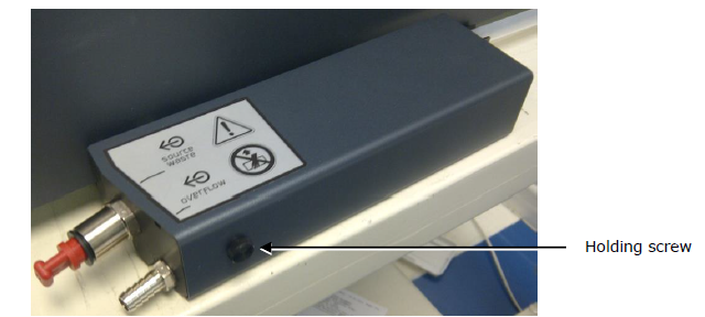
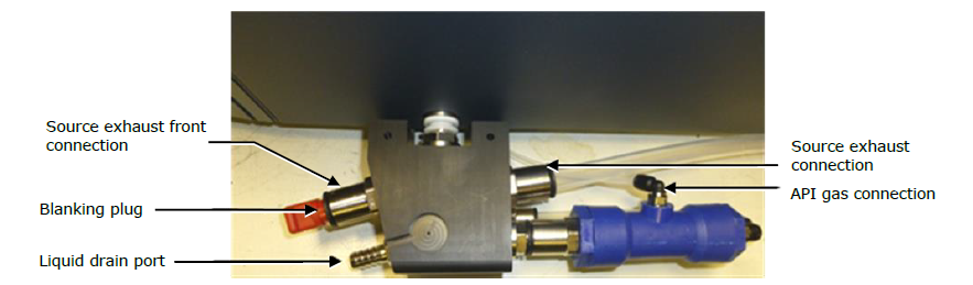
      • Remove the tube from the liquid drain port and from the source exhaust connection.                                                                                                                                                                                           clipboard_eb92c7c1d4dddd7b040234530a57c15ae.png
        • Reinstall the valve cover and the holding screw.                                                                                                                                                                                                                                         
    • If you have the integrated valve QDa version:
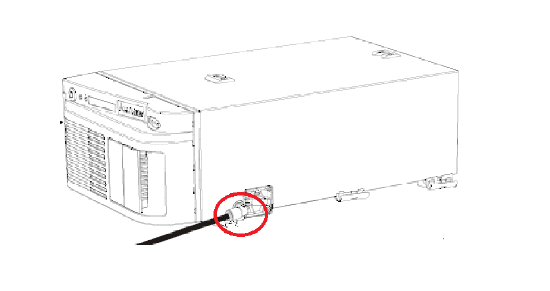
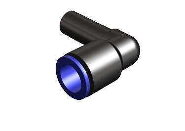
      • Remove the Elbow plug from the valve connector. (Remember to ship the elbow plug with the QDa.) clipboard_ee5d00e8c2eac18173dfa62bceed357c5.png  clipboard_e290843f528a81d183ac72035dfc97a02.png                                                                                                 
  5. Unplug and mark any cables (Ethernet, signal, I/O, events) from the module rear. 
    • For a QDa Standard, unplug the connections listed below:                                                                                                                                                                                 
      1. Ethernet 
      2. Nitrogen supply tubing
      3. Power cord
      4. Waste bottle solenoid control
      5. Diaphragm pump exhaust 
      6. Event cable                                                                                                                                                                                                                                                                                clipboard_e7bd3e1b46cd32eaa34b25ecb03c72c09.png
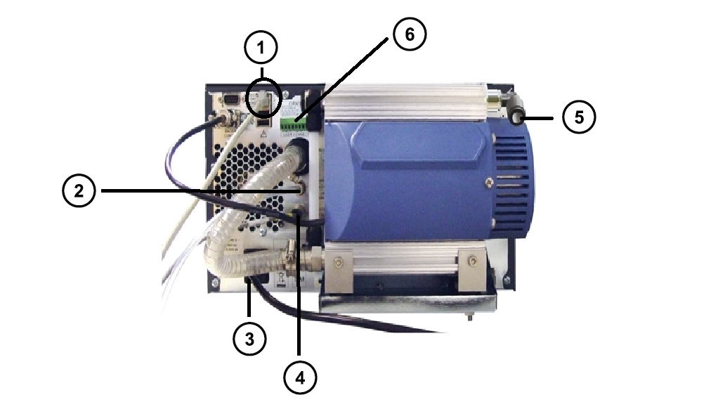
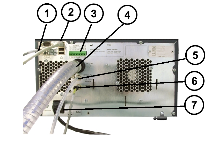
    • For a QDa Performance, unplug the connections listed below:                                                                                                                                                                      
      1. Backing pump control
      2. Ethernet port
      3. I/O signal connector
      4. Vacuum pump tubing
      5. Nitrogen inlet
      6. Waste bottle solenoid control
      7. Power cord                                                                                                                                                                                                                                                                                                                                    clipboard_ea086e82a8c961ffa029d73eeecd7dd7f.png
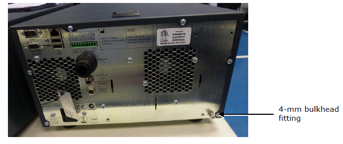
    • For instruments with an external drain assembly (serial number starts with KAA or KAB), on the rear, disconnect the drain tubing from the 4-mm bulkhead fitting.                                                                                                                                                                                                                                                                                                                                                                                                                                                                                                                                                                                                            clipboard_e51075c92d276fe253242333251c7d7b7.png
  6. Move the module to a suitable box for shipment. (If a box is not available, ask your local Waters office.)
      Note the dimensions and weight of the module to choose the appropriate box:                                                                    clipboard_e24a7f0c621d48856d6ac124c5aa3ba11.png
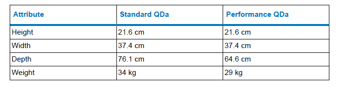
  7. Fill and sign the latest revision of the H&S module provided by Waters.
  8. Attach it to the box and send a PDF copy to the local Waters office.
  9. The Waters office will contact you to arrange the shipment.

ADDITIONAL INFORMATION

To reinstall the module, attach all of the cables and tubes that were removed.

id244388, QDA

Not able to find a solution? Click here to request help.