How to connect an Edwards RV5 oil-filled backing pump to a Waters ACQUITY QDa Detector - WKB197975
OBJECTIVE or GOAL
Connect an Edwards RV5 oil-filled backing pump to a Waters ACQUITY QDa detector.
ENVIRONMENT
- ACQUITY QDa Mass Detector
- Edwards RV5
PROCEDURE
Connecting the Edwards RV5 backing pump
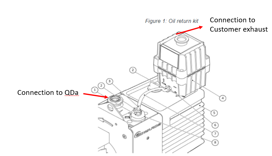
The Edwards RV5 pump has NW25 inlet and outlet ports. The RV5 pump will need the Oil Mist Filter, Part Number 6060139 Edwards EMF10 Oil Mist Filter, with oil return kit fitted to the outlet, exhaust, port.
Note: DO NOT USE THE BLACK NW25 PUMP ADAPTOR SUPPLIED IN THE OIL MIST FILTER KIT.
This is only supplied where the pump's exhaust port is fitted with a hose adaptor.
In order to connect to the existing QDa products, you must use a NW16-to-NW25 reducer (Waters part number 700009268) to connect the QDA Baking hose to the RV5 inlet port.
Fit the NW25 to the 3/8-inch hose nozzle (Waters part number 6070506) to the top port of the Oil Mist Filter.
For QDa systems, the Edwards RV5 pump has the oil return kit fitted, so no ballast is required. To install the Ballast Valve Adapter (#8) refer to the attached document Edwards RV5 installation steps.pdf.
Figure 1: Oil return kit
|
|
To connect the Edwards RV5 backing pump
NOTE: The switch box control is required for the Edwards RV5 pump.
- Position the pump on the floor, behind or underneath the instrument, and within 1 m (3.3 ft) of the rear chassis.
CAUTION: To prevent overheating, ensure that there is adequate ventilation around the pump.
- Connect the NW16 vacuum hose via the push-fit connection to the back of the instrument.
- Connect the other end to the rotary pump inlet using the NW16-to-NW25 reducer.
- Fit the oil mist filter to the Edwards RV5 pump's exhaust port, NW25 ,using a centerting ring and clamp.
- Do not use the pump exhaust adaptor (black) supplied with the oil mist filter - the Edwards RV5 pump already has a NW25 exhaust flange fitting.
- Connect the NW25-to-3/8-inch hose fitting piece to the top of the oil mist filter using a centering ring.
- Connect one end of the PVC exhaust tubing to the mist filter outlet nozzle using the Jubilee clip from the installation kit.
- Connect the other end of the exhaust tubing to a suitable laboratory air extraction system.
CAUTION: To prevent electrical shock, ensure that the laboratory mains power supply is switched OFF and isolated before connecting power cables.
6. Make sure correct voltage on pump is selected. The arrow shown on the pump points to what the pump is rated to for the voltage. (e.g. For countries that use 110-V power supply (for example, the US). "200 V 50 Hz/200-210 V 60 Hz" (Japan).
US: 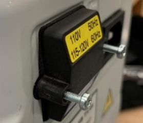 Japan:
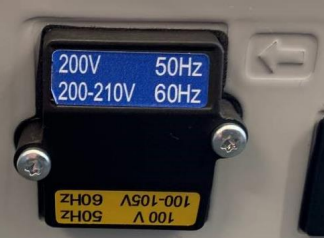
- Connect one end of the power cable (pump to switch box) to the Edwards RV5 pump.
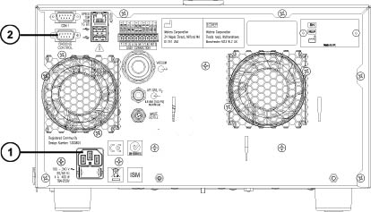
- Connect the laboratory mains supply cable to the rear of the instrument (Figure 2).
- Connect one end of the pump control cable to the backing control port on rear of the instrument (Figure 2).
Figure 2: QDa rear panel and connection to pump control cable
 |
|
CAUTION: To prevent electrical shock, ensure that each power cable is disconnected from the mains power source before connecting each power cable to the switch box.
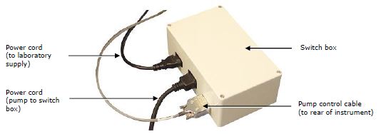
- Ensure that the pump power switch is set to ON and attach the three cables to the switch box (Figure 3).
Figure 3: Switch box control
ADDITIONAL INFORMATION
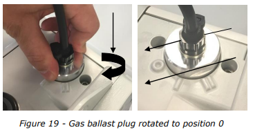
BALLAST Knob should be set to 0 when running.
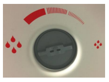
VACUUM Knob should be set to the smaller droplets for higher vacuum mode.
id197975, QDA