How to replace the needle seat port assembly on an ACQUITY Sample Manager - Flow Through Needle (SM-FTN) - WKB302098
OBJECTIVE or GOAL
Replace the needle seat port assembly on an ACQUITY Sample Manager that uses the flow-through-needle style injector (SM-FTN).
ENVIRONMENT
- ACQUITY UPLC H-Class
- ACQUITY UPLC H-Class Bio
- ACQUITY UPLC H-Class PLUS
- ACQUITY UPLC H-Class PLUS Bio
- ACQUITY UPLC Sample Manager - Flow Through Needle PLUS (SM-FTN PLUS)
PROCEDURE
This procedure describes how to replace the needle seat port assembly in several of the ACQUITY Sample Managers that use the flow-through-needle style injector (SM-FTN).

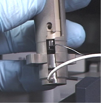
Figure 1 - Needle seat port assembly

Tools/materials required
• Torx screwdrivers: T10, T20
• Wrenches: 1/4-inch, 5/16-inch
• Wire cutters
• Needle-nose pliers
• Clean, chemical-resistant, powder-free gloves
Safety advisories
Review the safety advisories before beginning the procedure.
Removing the inject/wash station
1. From the console, click on the SM-FTN in the system tree.
2. From the menu bar, click Maintain > Replace Seal.
Note: A reminder appears to characterize the needle seal, prime the system, and perform the pump dynamic leak test after replacing the needle.
3. Click OK.
Note: A second message reminds you to click Reset to return the instrument to normal operation and to keep clear of the sample chamber after replacing the hardware.
Warning: The needle carriage moves to the rear of the sample compartment. A message appears warning you that the needle will move when the action is accepted and to keep clear of the chamber.
4. Turn off the power to the unit and disconnect the power cord at the rear.
5. Loosen the two captive T20 screws (Figure 2) that secure the access panel, and then remove the panel.
Figure 2 - Removing the front access panel screws

6. Disconnect the needle seat port assembly tubing from port 1 on the injection valve using the 1/4-inch open-end wrench (Figure 3).
Figure 3 - Disconnecting the needle seat port assembly tubing

7. Remove the T10 screw that secures the inject/wash station to the sample compartment floor (Figure 4).
Figure 4 - Removing the T10 screw

8. Lift the assembly upward and remove it from the sample compartment (Figure 5).
Figure 5 - Removing the inject/wash station

Disassembling the inject/wash station
1. Unscrew the needle wash tube from the wash fitting, and then unscrew the wash fitting from the inject/wash station. While holding the assembly in a vertical position, slide the support sleeve out of the metal housing and guide the needle seat port assembly tubing up through the slots (Figure 6).
Figure 6 - Extracting the sleeve and needle seat port assembly tubing
Rebuilding the inject/wash station
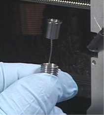
Figure 7 - Needle seal wash housing assembly

1. To help ensure that the components within the inject/wash station's metal housing remain in place, place back in place on the compartment floor (Figure 8).
Figure 8 - Repositioning the metal housing

4. Cut the old needle seat port assembly tubing from the lock nut using wire cutters (Figure 9).
5. While holding the PEEK support sleeve with the 1/2-inch open-end wrench, loosen the lock nut using the 5/16-inch open-end wrench and unscrew the support sleeve from the lock nut, and then discard the old tubing.
Figure 9 - Opening the support sleeve

6. Insert a needle seat port assembly tubing through the lock nut (Figure 10) and route the tube down until the flanged cup is seated properly in the lock nut.
Figure 10 - Installing new cup/tube into lock nut
7. Gently set the tubing to a 90-degree angle where it exits the locknut - avoid crimping this tubing (Figure 11).
Figure 11 - Proper bend in tubing

Important: To avoid interfering with the motion of the metal spring in the metal housing, the bend in the seal tubing must not extend beyond the step in the lock nut (Figure 11).
8. Insert a new Vespel seat (large-seal side facing up) into the needle seat port (cup)
(Figure 12).
Figure 12 - Installing the Vespel seat

9. Insert the needle seat port assembly with Vespel seat into the bottom of the support sleeve
(Figure 13).
Figure 13 - Installing the Vespel seat assembly

10. Finger-tighten the support sleeve onto the lock nut.
11. While holding the PEEK support sleeve with the 1/2-inch open-end wrench, tighten the lock nut 1/4-turn past finger-tight using the 5/16-inch open-end wrench (Figure 9).
Important: To avoid interfering with the motion of the metal spring in the metal housing, the bend in the seat tubing must not extend beyond the step in the lock nut (Figure 11).
Important: The needle seat port assembly tubing should be in alignment with the threaded wash fitting hole in the support sleeve (Figure 14).
Figure 14 - Aligning the needle seat port assembly tubing

12. Ensure that the load cell and spring cup are properly positioned in the inject/wash station (Figure 15).
Figure 15 - Proper positioning in the inject/wash station

13. Slide the needle seat port assembly tubing into the slot on the side of the metal housing (Figure 16).
Figure 16 - Proper assembly alignment

14. Being careful not to cross-thread the wash fitting, carefully screw it into the support sleeve (Figure 17).
15. Screw the wash tube into the needle wash fitting, and tighten it 1/4-turn past finger-tight
NOTE: The black PEEK wash fitting is fragile; do not overtighten.
Figure 17 - Installing the wash tube

Important: When sliding the support sleeve into the metal housing, ensure that the fitting hole of the support sleeve aligns with the slot on the metal housing (Figure 17).
It is extremely important that the three prongs on the lock nut are seated inside the metal spring.
Installing the inject/wash station
1. Align the screw hole of the inject/wash station with the hole in the compartment floor.
Be aware that there are unused holes in the sample compartment floor (Figure 4).
2. Ensure that the inject port wash drain is in the needle wash basin (Figure 4).
Note: The wash tube is secured to the wall and should not interfere with the sample tray operation or vertical motion of the wash port.
3. Secure the inject/wash station to the chassis with the T10 screw (Figure 4).
4. Insert the needle seat port assembly tubing into port 1 on the injection valve. With the tubing and ferrule assembly bottomed in the port, thread the fitting into the port and tighten the 1/4-inch fitting (Figure 3).
5. Ensure that the load cell cable is not in the way of the needle carriage assembly (Figure 1).
6. Replace the access panel and ensure that the seal extension tube is routed through the cutout
(Figure 2).
Important: To reduce rotational stress on the inject/wash station, the wash tube and needle seat port assembly tubing must be routed in front of the load cell cable as shown in Figure 18.
Figure 18 - Proper cable/tubing routing

Verifying the procedure
Verify that the procedure is satisfactorily completed and that the system is functioning properly.
1. Power-on the instrument and allow the unit to go through initialization diagnostics.
- Successful initialization of the instrument is indicated by a steady green power LED and an unlit run LED.
- Unsuccessful initialization of the instrument is potentially indicated by a steady red or flashing red run LED, or by the display of an error in the Console.
To troubleshoot, refer to troubleshooting information for your system.
2. Calibrate the needle z axis.
3. Characterize the needle seal.
4. Perform the needle seal readiness test.
ADDITIONAL INFORMATION
id302098, A-30SM, DLT, UPISMFTN, UPPFTN, UPQSM, UPQSM+, UPQSMBIO, UPQSMBIO+, UPSMFTN, UPSMFTN, UPSMFTN+, UPSMFTN+, UPSMFTNB+, UPSMFTNBIO