Calculating USP signal-to-noise - Tip308
OBJECTIVE or GOAL
Calculate USP signal-to-noise using a specified time region in the blank for the noise.
ENVIRONMENT
- Empower
- Tip of the Week #308
PROCEDURE
STEP 1
USP signal-to-noise (S/N) is calculated as 2xHeight of peak/noise (Figure 1).

STEP 2
From the Sample Set Method, Blank is the label for the blank injection, and there is only one injection. This is single-channel UV data, so there is no need to specify the channel (Figure 2).

STEP 3
Create a peak Custom Field using intersample syntax. We need the Scale to µV field in the equation because peak height is in µV (microvolts) and peak-to-peak noise is in detector units, which in this case is AU (Figure 3).

STEP 4
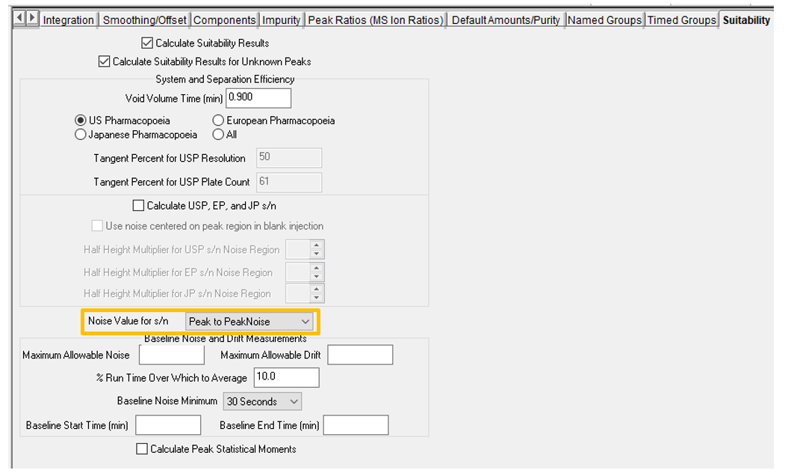
Go to the Suitability tab in the Processing Method and select peak-to-peak noise from the Noise Value for s/n drop-down menu (Figure 4).

STEP 5
Go to the Noise and Drift tab in the Processing Method and select the time region from the blank injection from which peak-to-peak noise will be calculated (Figure 5).

STEP 6
After the Sample Set is processed, take the Result Set into Review. Go to the Results window, and in the Chromatogram Result table we can see the peak-to-peak noise calculated from the blank injection (Figure 6).

STEP 7
Click on a result for one of the standards or samples. The Custom Field is calculated based on the noise from the blank injection specified in the Custom Field (Figure 7).

Important Note: Peak-to-peak noise will be calculated for every injection. However, it is the peak-to-peak noise from the blank injection that is used to calculate signal-to-noise for all peaks in all injections.
ADDITIONAL INFORMATION
This can be done with either the Pro or QuickStart interface.

